Production Equipment Items for OEE
OEE Production configuration:
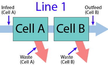
Model the Production Line
How you model a production line in the Production Model will be dependent upon the following factors:
- Type of Line (single machine, simple contiguous process, parallel processes, shared cells across lines, complex sub-lines, primary cells, cell groups within cell groups)
- Line Downtime Determination (When is the line considered to be down? All cells, any cells, particular cell)
- How production is scheduled (if parts of a line are scheduled separately from each other, then they may be considered two separate lines)
- Interface to cell (if a cell has no real-time accessible interface, its state and output may be combined with an adjacent cell)
- Reporting for the Line (What do I need to report on and show to users?)
The importance of modelling the line correctly based on the above factors will drive the usability and usefulness of any production data or metrics generated. If a production line of many cells is modeled simply as a single cell, then features provided by the OEE module such as downtime detection methods, cell cycle time, aggregation of machine states by cell, and visual aspects of the OEE components such as the OEE Time chart will all be diminished. Forcing management to schedule production runs on multiple lines that they did not do prior to the OEE implementation, as well as only allowing a single scheduled run on a a set of cells where traditionally multiple schedules existed are signs that the model may not be correct.
In modelling the Line, you will create a Production Model in the Designer that:
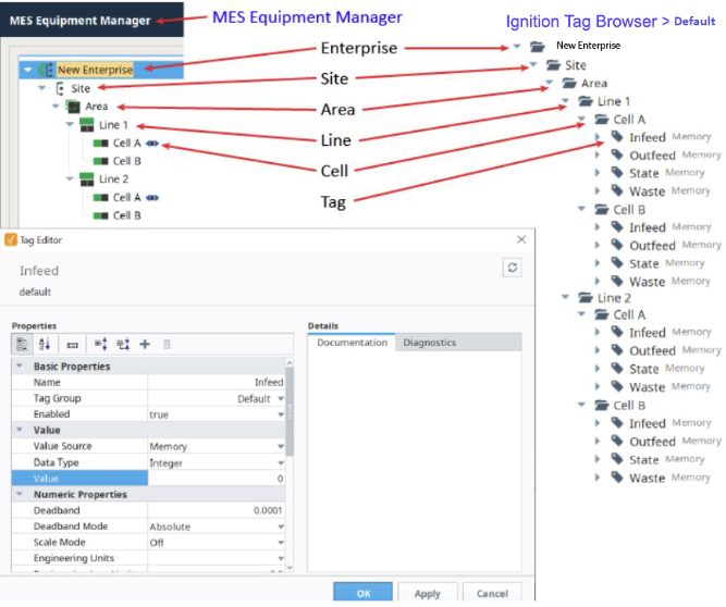
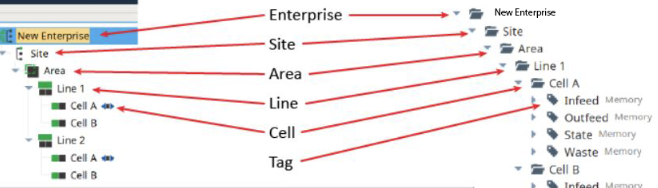
- Defines your Enterprises Sites, Areas, Lines and Cells
- Sets up Downtime Detection Modes to define how Line downtime is determined
- Connects states and counts from the equipment PLC interface to the production model
Add Equipment Items in the Production Line
To complete this step you need to have the Equipment Manager component on a Perspective view. Equipment Manager is installed in the Production Module.
For information, see Line Settings.
In Equipment Manager:
-
Create a new Site. Name it: Site.
-
Create an Area named Area.
-
Create a Line called Line 1.
- Under Line 1, create two Cells called Cell A and Cell B
- Click Line 1 and then click Downtime Detection Method in the OEE section on the right. Change the Downtime Detection Method to Key Reason (Cell Priority). Click Save.
- Click Line 1 and then click the Copy icon in the Tool Bar.
- Using Paste in the Toolbar, now paste a new Site branch in the node named Area.
Select a Key Cell
- Select Cell A in Line 2 and click the Set Key Cell icon in the Toolbar.
Create Tag Structure
Tags serve as a flexible data model within Ignition and the link between MES functionality and the plant floor. Creating the tag structure with the same hierarchy as the standards based Equipment Model in the Equipment Manager allows for reuse of equipment addresses and rapid project deployment with parameterization.
Add Default Tag Group
To add the Default Tag Group:
-
In Ignition Designer >Tag Browser, click the three dots on the right side of the panel.
- Click the Plus icon to add a new tag group and name it: Default.
- Click OK.
Create Tag Folders

|
You create the Tag paths to match the Production Model. Doing this makes the "{Equipment Path}" prefix valid in references. |
In Ignition > Tag Browser:
Create a tag structure to match the items in the Production Equipment Model.
-
Select Default from the Tag Browser dropdown.
-
Click the Plus icon, and select New Folder, or right-click menu, New Tag > New Folder.
-
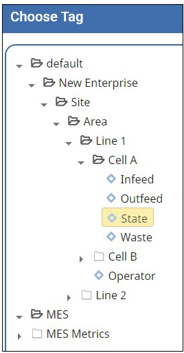
Create the following folder tree. This structure must match the the Production Equipment Model items that you will soon set up in Equipment Manager:
- Create a Site folder called Site.
- Create an Area folder called Area.
- Create two Line folders called Line 1 and Line 2.
- In both the Line 1 and Line 2 folders, create Cell folders called Cell A and Cell B.
Create Tags
-
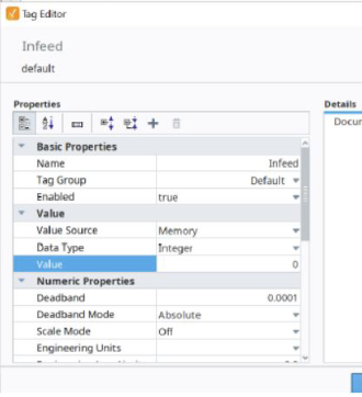
In the Cell A of Line 1, create 4 Memory Tags as data type Integer:
- Infeed
- Outfeed
- Waste
-
State
-
Highlight all four tags, right-click and select Copy.
- Paste into Line 1 > Cell B.
- Then, paste into Line 2 > Cell A and Line 2 > Cell B.
Required Framework:
Tag Editor
Create MES Counters
The Tags you just created will drive OEE functionality via MES Counters configured for Cell A and Cell B. They can also be created at the Line level.
The counters are used to calculate OEE Performance and OEE Quality as well as track production output, scrap, etc.
For details, see MES Counters and Counter Groups.
- In Equipment Manager, click Line 1 > Cell A.
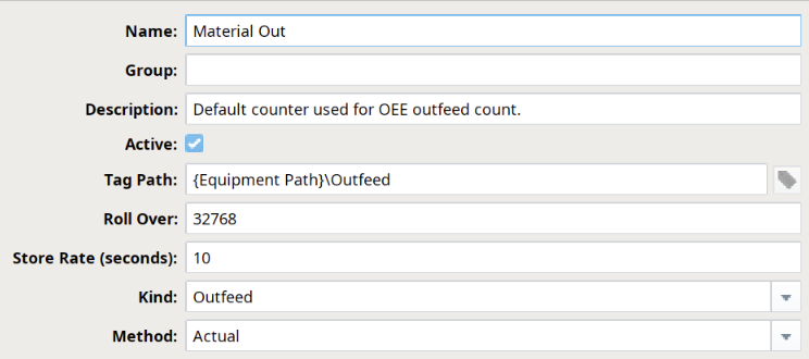
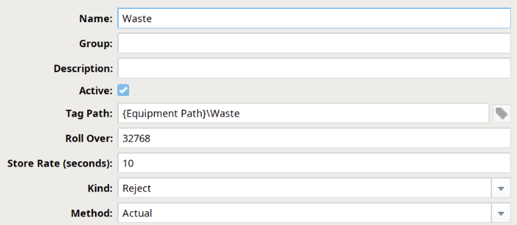
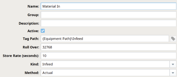
- In Edit Counter, configure like this:
|
Material In and
Material Out counters |
||||||||||||||||
|---|---|---|---|---|---|---|---|---|---|---|---|---|---|---|---|---|
|
Tag Path: {Equipment Path}\Outfeed References the path to the Tag Provider in Ignition. Manually change, bind to PLC counter, Memory Tag or SQL data value. Best Practice: Parameterized Tag Paths here which allows for indirection and exported MES Counters to be easily deployed to other equipment. Store Rate: Change to 10 (seconds) Captured and stored in the database after this specific interval in seconds if the value has changed. If the Store Rate is set to zero, every value change is recorded Best Practice: The default value is 60. If your PLC produces values at a very high rate, you should leave the Store Rate near its default value, since zero would result in a very high quantity of data being stored. This can cause slower analysis results as time progresses. Since the minimum interval for analysis examination is one minute, you will likely find that leaving your Store Rate at 60 will provide much faster system performance than setting it to 0 (every value change recorded). Kind: Outfeed Infeed, Outfeed and Reject kinds are used solely by the OEE module to determine which MES counter to use for OEE Performance, OEE Quality and production count information. The General kind can be used for any other count value.
When an OEE Line does not define a reject counter, rejects are determined automatically by the OEE module in this way:
OR
Method: Actual The Actual count mode simply uses whatever value is passed through the Tag specified in Tag Path to represent the actual production counts. Production counts can go down as well as up.
|
|
|||||||||||||||

|
Downtime Detection Mode | How Downtime is Determined For detailed information about detection modes, see Downtime Detection Modes. |
Add a Memory Tag for Additional Factor
Additional Factors represent values that can be used as comparators for analysis, adding context to plant floor activity. The unique thing about Additional Factors is that they are not part of the default data collection set (e.g. Mode, State, Production Counts, Work Order, etc.). Therefore, they represent a simple configuration to customize analysis options for an end-user. Common examples of Additional Factors are supplier information, tooling information, or personnel information (e.g. "Tooling: Robot Tool Head 123", "UserID: Tim", etc.). So long as you can write a single value to an Ignition tag, you can populate an Additional Factor and leverage it within the OEE Downtime module.
In Ignition, in Tag Browser:
- Select Default from the Tag Browser dropdown.
- In Line 1, new Tag, type Memory.
- Name it Operator.
- Next, add the Operator Additional Factor to Line 2.
Add an Additional Factor for Lines
In Equipment Manager:
- Select Line 1 and under General > Additional Factors.
- Highlight Additional Factor and click Edit.
- Enter the configuration shown in this screenshot:
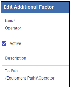
- Next, repeat these steps for Line 2.
Add State Tags for OEE in Perspective
OEE calculations require State inputs at the Cell and/or Line level, to know the overall state of that line's operations. In this tutorial, we will use a State memory Tag in each Cell to simulate the state of each Cell. Review the Equipment Modes and States model.
-
In the Equipment Manager, click to highlight Line 1 > Cell A.
-
Under General, click Tag Collectors.
- For Equipment State, navigate to and select the State tag. The Tag Browser is exposed here.
- Save and close.
- Repeat for the other three Cells pointing to the State Tag in that Cell's corresponding Tag Browser folder).
Add a Equipment State for Unplanned Downtime
Equipment states and modes describe the status of equipment, both at the local, physical level (State), as well as the logistical level (Mode).
Each piece of equipment has the potential to have it's own running and downtime states, as well as asset utilization categories (Mode) therefore, extending the default set of states and modes may be necessary. In this section, you'll be extending mode and state lists.
In Equipment Manager:
-
Select Line 1 and on the right, click OEE > State Class.
-
Select Default and click the Plus icon.
- Add an Equipment State and name it Aborting.
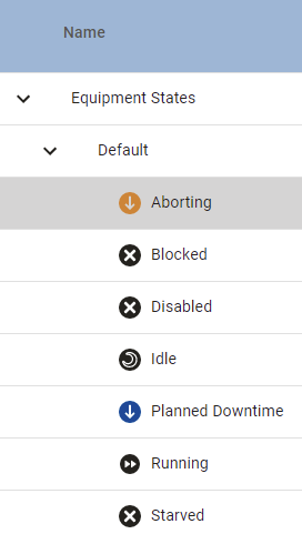
-
Type: Unplanned Downtime.
-
Code: 99
-
Short Stop Threshold: 10 seconds.
- Click Save.
Add New Equipment Mode
In the Equipment Manager:
- Select Line 1 and click Mode Class.
- Add a Mode Class named Training
- Add a Mode State named Training_SlowSpeed.
- Set Type to Production.
- Set the Code (the default will be the next available integer).
- Set the checkboxes for Include in OEE and Include Production Counts.
- Save.
Add Material
The Material Root is the base class for all OEE Material Classes and Definitions. All materials used in OEE Downtime operations (e.g. production runs, etc.) and those created using OEE Material Manager component are children of the Material Root. There is only one Material Root object per Ignition Gateway instance. The Material Root object cannot be edited or deleted.
In Material Manager:
-
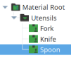
Add a new Material Class (under the Material Root).
Example (Name = Utensils):
-
Add several Material Definition items to the new Material Class.
Example (three created, called Fork, Knife and Spoon):
-
While creating each Material Definition, click to select Line 1, as shown below, then configure the MES counters as follows:
- Enable the material to be run on Line 1 by setting the checkbox.
- Make sure that Auto End Changeover is enabled (default):
- Set the Infeed Count Equipment to Cell A (incoming material is counted as it enters the first Cell in the Line).
-
Set the Outfeed Count Equipment to Cell B (outgoing material is counted as it leaves the last Cell in the Line).