Sepasoft MES Module Suite
Configuring Equipment States
Equipment States represent the status of the line (or cells within a line) that provide an indication of whether the equipment is off-line, idle, running, faulted, blocked, starved, Clean in Place (CIP), etc. It is entirely separate from the equipment mode, which provides a logistical view of intended purpose. The equipment status will generally come from a PLC tag that provides real-time state information of the equipment, but can really come from any source that can populate an Ignition tag. This allows for manual entry screens of operator input equipment state or data parsed from a flat file entry.
Equipment States can be grouped, allowing multiple states to be considered as Running by OEE i.e. loading, heating, molding → running. They allow for the tracking of specific events that may prevent a line or cell from running. Some reasons are considered causes of line downtime where others are not. As an example, if a cell on a production line becomes blocked as the outfeed from it backs up and there is no room to discharge product it will stop. In this example, it is simply normal operation for the cell and not the cause of the production line not producing product. A cell further down the line is the cell preventing the production line from producing product. Other downtime reasons may be planned. Any time that the production line is scheduled around breaks, lunches, safety meetings, disabled shifts, etc., is planned and will not count against the production line OEE Availability. The current state is captured from equipment via tag values passed to the state tag collector in the production model.
Core Concepts of Equipment States
- Function: They indicate whether equipment is off-line, idle, running, faulted, blocked, starved, undergoing Clean in Place (CIP), or in another defined condition.
- Distinction from Equipment Mode: Equipment State is entirely separate from Equipment Mode, which provides a logistical view of the equipment's intended purpose.
- Data Source: The status is typically derived from a PLC tag providing a real-time integer value. However, the source can be anything capable of populating an Ignition tag, including manual operator entry screens or data parsed from a flat file.
More information:
- Refer to OEE Downtime Settings > Equipment State for more details.
- The MES Equipment Manager component is used to change equipment mode class, state and schedule.
Obtaining Status Values for Cells on a Production Line
The OEE module determines the equipment state from a single numeric integer value. Single numeric values are stable and can only represent one state. There is no limit to the number of equipment states that can be defined other than by the maximum numeric value your PLC can handle.
When the OEE module detects a production line or cell state change, it will lookup the downtime reason from the state value. If communication to the PLC fails, in the case when an electrical connection is shut off, the production line or cell state is replaced with 0. If this happens during a production run, it will count as downtime if configured as such.
Line Downtime Versus Cell Downtime
It is important to understand the difference between line downtime and cell downtime. Line downtime is created by events that prevent the production line from producing product, and is typically used to focus on improving OEE. Cell downtime is used to look at trends and detect maintenance issues before they cause line downtime. Consider a production line that has 25 cells. If 5 of the cells are down all at the same time for unrelated reasons and only one of them is preventing product from being produced on the line there will be a lot of noise (extra irrelevant data) to weed through. Also, if a faster downstream cell stops, restarts and catches up, it may never affect the production of the line as a whole. The OEE Downtime Module provides the best of both worlds and tracks both line downtime and cell downtime.
After an automatic reason has been triggered, the operator can override it with a more specific reason. Both are logged and can be viewed in analysis and reporting. For details about how to disable manual override see the Editable property in the Downtime Table.
More information:
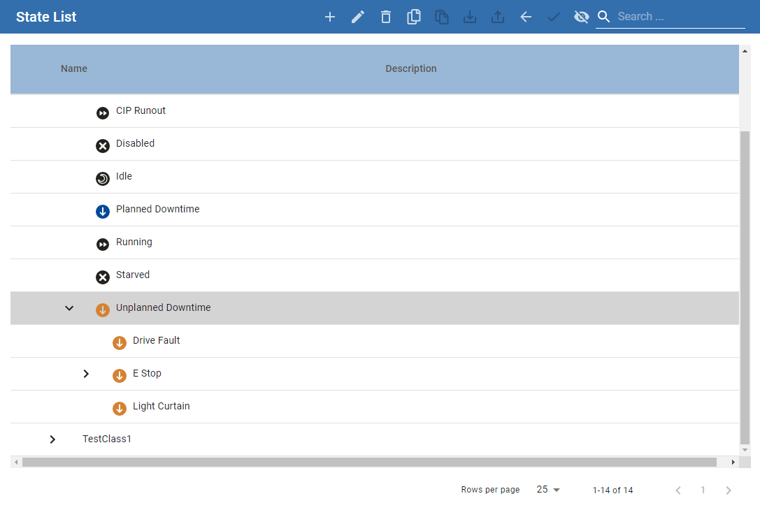
Default Equipment State Class
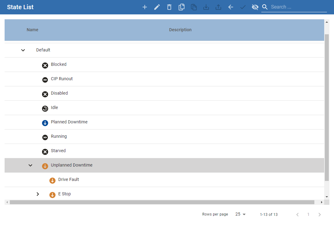
Equipment manager component by default has an equipment state class named Default. The default class consists of the following default states.
- Blocked
- Disabled
- Idle
- Planned Downtime
- Running
- Starved
- Unplanned Downtime
Adding and Editing Equipment State Classes
- Organization: The class holds and organizes the specific states that an equipment item (line or cell) can be in, such as Blocked, Disabled, Idle, Planned Downtime, Running, Starved, and Unplanned Downtime. You add new Equipment States to a selected Equipment State Class.
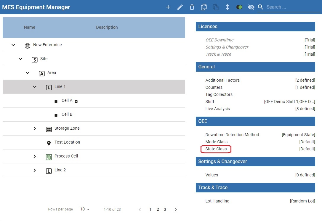
- Configuration Access: The MES Equipment Manager component is where you select the production model item and click on State Class to begin editing it.
- Management Operations: At the Equipment State Class level, operations like Edit, Delete, Copy, Paste, and Export are available.
- Security Control: You can assign security roles to an Equipment State Class to specify who can modify it.
- Hierarchy: It is possible to create nested state classes by adding an equipment state class to an already existing one.
- Default Initialization: The class controls the default settings for new states added to it, specifically regarding line downtime overriding. The Default Override Current Line Downtime property on the class initializes the
Override Current Line Downtimecheckbox for any new State added to that class.
To manage state classes:
- Open an MES Equipment Manager component.
- Select the production model item for which the equipment state class is to be changed.
- Click on State Class to begin editing.
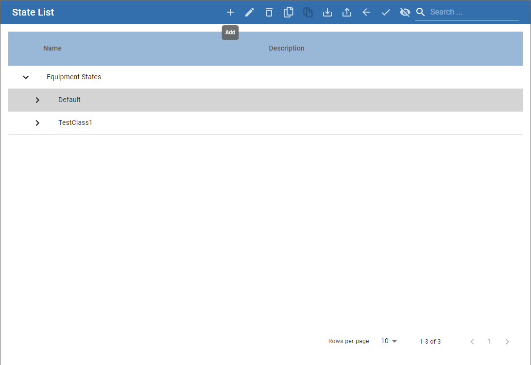
- The State Class window appears. Highlight Equipment States and click the Add button (indicated by the plus icon). In the resulting contextual menu, select New Equipment State Class.

|
|
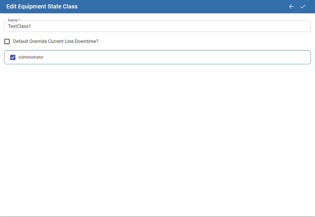
- Enter a name for the new Equipment State Class and assign security roles you who can modify this Equipment State Class.
- Click Save.
Default Override Current Line Downtime
This checkbox (False in the screenshot, but checked by default) causes any new State added to the class to have its Override Current Line Line Downtime checkbox initialized as True (checked). Checking or unchecking this box does not cause any existing child State to have its override setting changed.
This property is available on the MES Equipment State Class Object for use via scripting.
Adding and Editing Equipment States for an Equipment State Class
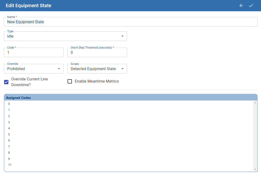
Property | Description |
Name | A descriptive name for the state (e.g., "E-Stop", "Quality Issue"). |
Type | The fundamental category of the state. Valid types are: Unplanned Downtime, Planned Downtime, Blocked, Starved, Running, Idle, and Disabled. |
Code | The unique integer value that corresponds to this state, typically matching a status code from a PLC. Note: Do not use the value 0, as it is reserved for communication failures. |
Short Stop Threshold (seconds) | The duration a state must persist before it is officially logged and counted against OEE Availability. Events shorter than this threshold are ignored. Setting this to 0 ensures all events are included. This threshold is not applied to states of the Running type. |
Override Current Line Downtime | A boolean ( True/False) setting affecting Key Reason detection (Cell Priority and Neighbor Priority methods). If True (default), this state can override the line's current downtime reason. If False, it cannot. This is critical for determining the correct root cause of a line stoppage. |
Enable Meantime Metrics | If enabled, this state will be included in the calculation of Mean Time Between Failure (MTBF) when it is the cause of a line downtime event. MTBF is calculated as: Total Running Time / Number of Applicable Events. This is most pertinent for Unplanned Downtime states. |
Override | Defines operator permissions for changing this state in the Downtime Table Editor. Options are: Optional (can change), Prohibited (cannot change), and Required (must change to a more specific reason). |
Scope | Works with the Override property to define the list of states an operator can select. Options are: Detected Equipment State (states for the specific cell), Any Equipment State (states for any cell on the line), or Sub State (only nested sub-states). |
- To edit an existing Equipment State, click to highlight it and then click the Edit button (pencil icon).
Or:
- To add a new Equipment State, select the Equipment State Class you wish to add a state to and click the Add button (plus icon). Note, you can also select an Equipment State before selecting the Add button to create a state nested under a parent state.
- Enter a name for the state and select the type of state. Valid Equipment State Types are:
Unplanned Downtime
Planned Downtime
Blocked
Starved
Running
Idle
Disabled
- Assign a unique code to the new state. This is used if you drive the state of the equipment through a tag.
- Click Save.
Code
Enter in the integer value for this equipment state. This will generally align with the status code value from the PLC.
Note:

|
Do not set state code to zero, since zero is used internally. |
Assigned Codes
The Assigned Codes list provide a view of all codes that have already been assigned.
Short Stop Threshold (seconds)
Enter in a time value in seconds for how long a state must persist for before it considered to be in this. The Short Stop Threshold is not used for states of state type RUNNING.
Down Time events can be prevented from affecting OEE Availability for a set duration of time (Short Stop Threshold). Events that occur during the Short Stop Threshold period will be ignored for ongoing OEE Availability calculations. To have all events be included in OEE Availability calculations, set Short Stop Threshold = 0.
Override Current Line Downtime
Note: This setting only affects the Key Reason detection methods, Cell Priority and Neighbor Priority.
- When this checkbox is checked (True, default condition), then this state is allowed to override the current downtime reason of the Line.
- When this checkbox is unchecked (False), the this state is not allowed to override the current downtime reason of the Line.
This property is available on the MES Equipment State Object for use via scripting.
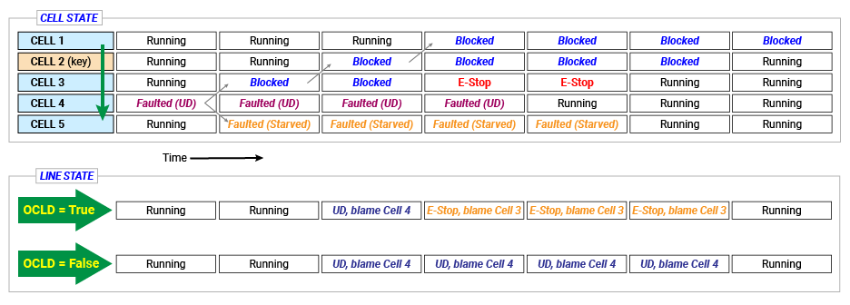
Example
In this example, there is a production line with 5 cells, Cells 1 through 5. Cell 2 is the key cell.
7 Steps:
- Cell 4 goes down with an Unplanned Downtime state.
- Cell 3 becomes blocked
- Cell 2 becomes blocked, and as a result, the Line goes down blaming Cell 4, correctly.
- While this is happening, an Operator on Cell 3 presses the E-Stop button to clear the clogged parts from the machine.
- Cell 4 resumes functioning.
- At some point thereafter, the operator finishes his repairs on Cell 3 and returns the cell from E-Stop to Running.
- Cell 2, the key cell, becomes unblocked.
If the E-Stop state has the Override Current Line Downtime box CHECKED (True, default behavior), then below is the LINE STATE (in Key Reason (Cell Priority)) at each of the above 7 steps:
- Running
- Running
- Unplanned Downtime, blaming Cell 4
- E-Stop blaming Cell 3
- E-Stop blaming Cell 3
- E-Stop blaming Cell 3
- Running
If the E-Stop state has the Override Current Line Downtime box UNCHECKED (False), then below is the LINE STATE at each of the above 7 steps:
- Running
- Running
- Unplanned Downtime, blaming Cell 4
- Unplanned Downtime, blaming Cell 4
- Unplanned Downtime, blaming Cell 4
- Unplanned Downtime, blaming Cell 4
- Running
Cell/Line behavior diagram of above scenarios:
Enable Meantime Metrics
When enabled, this state will be included in the calculation of Mean Time Between Failure (MTBF), when this state is responsible for causing a line downtime event. MTBF is calculated by taking total running time, or time during a run in which the line is not down, and dividing it by the number of applicable events. So if a production run had 3.5 hours of running time and had 5 events for which Meantime Metrics were enabled, the MTBF would be 0.7. MTBF is pertinent for unexpected downtime events or Unplanned Downtime Type states.
Override
The Override property defines if it is possible for a operator to override the equipment state through the Downtime Table Editor component. Valid options are:
- Optional - Operator can select a different state based on the Scope setting
- Prohibited - Operator cannot change this equipment state
- Required - Operator is required to select a state based on the Scope setting for this equipment state
Scope
The scope setting is used by the Override setting to provide a set of operator selectable equipment states. Valid Options are:
- Detected Equipment State - operator can only select from list of equipment states for the equipment (cell)
- Any Equipment State - operator can select from list of equipment states for any piece of equipment (cell) on the Line
- Sub State - operator can only select from list of sub states created under this Equipment State.
Sub States
It is possible to create Equipment States under Equipment States. These are known as Sub States and can be used to group States together that can be used with the Scope Function to allow operators to select specific states (or Downtime reasons) based on the original equipment state.
Example - Stamping Press state is set to 'Quality Issue'. The Scope for 'Quality Issue' is set to 'Sub-State' and Override is set to 'Required'. Whenever a 'Quality Issue' state occurs on the Stamping Press that results in a line downtime event, the operator must select one of the sub-state reasons such as 'O2 Deviation', 'Wrong Color' or 'Burr on Mold'.
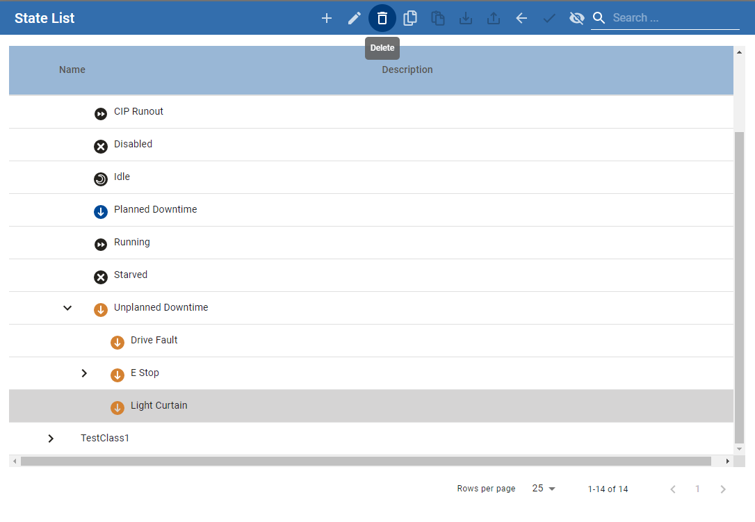
Delete Equipment State
- Click on the Equipment State to be deleted and click the Delete button (trashcan icon).
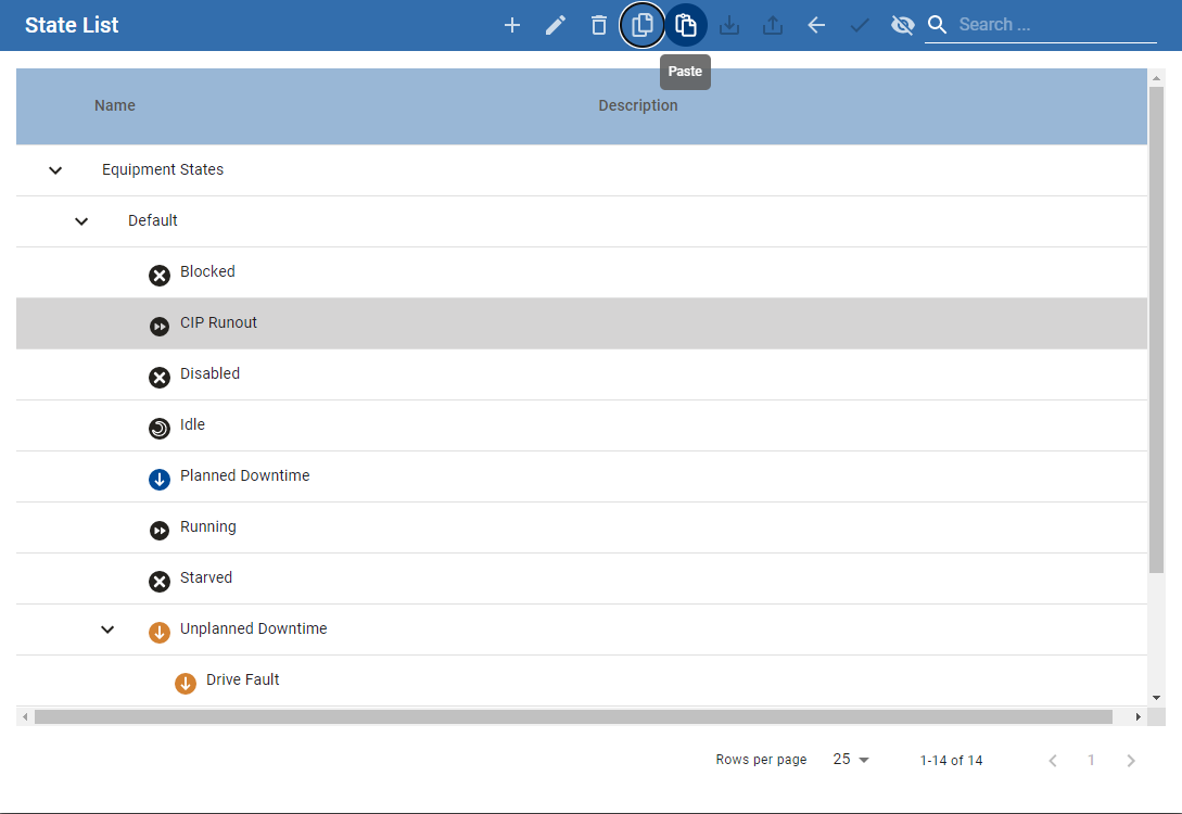
Copy and Paste Equipment State
- Select the Equipment State to be copied and click the Copy button.
- Select the Equipment State Class to which the state is copied and click the Paste button.
Export and Importing Equipment States
The entire Equipment States hierarchy or individual classes can be exported to an .xml file. This allows for backup, versioning, and easy transfer of state configurations between systems by importing the .xml file.
Export
- To export, select Equipment States and click the Export button, or right click on Equipment States and click the Export menu item.
- A file save dialog box will appear allowing you to select where to store the .xml file.
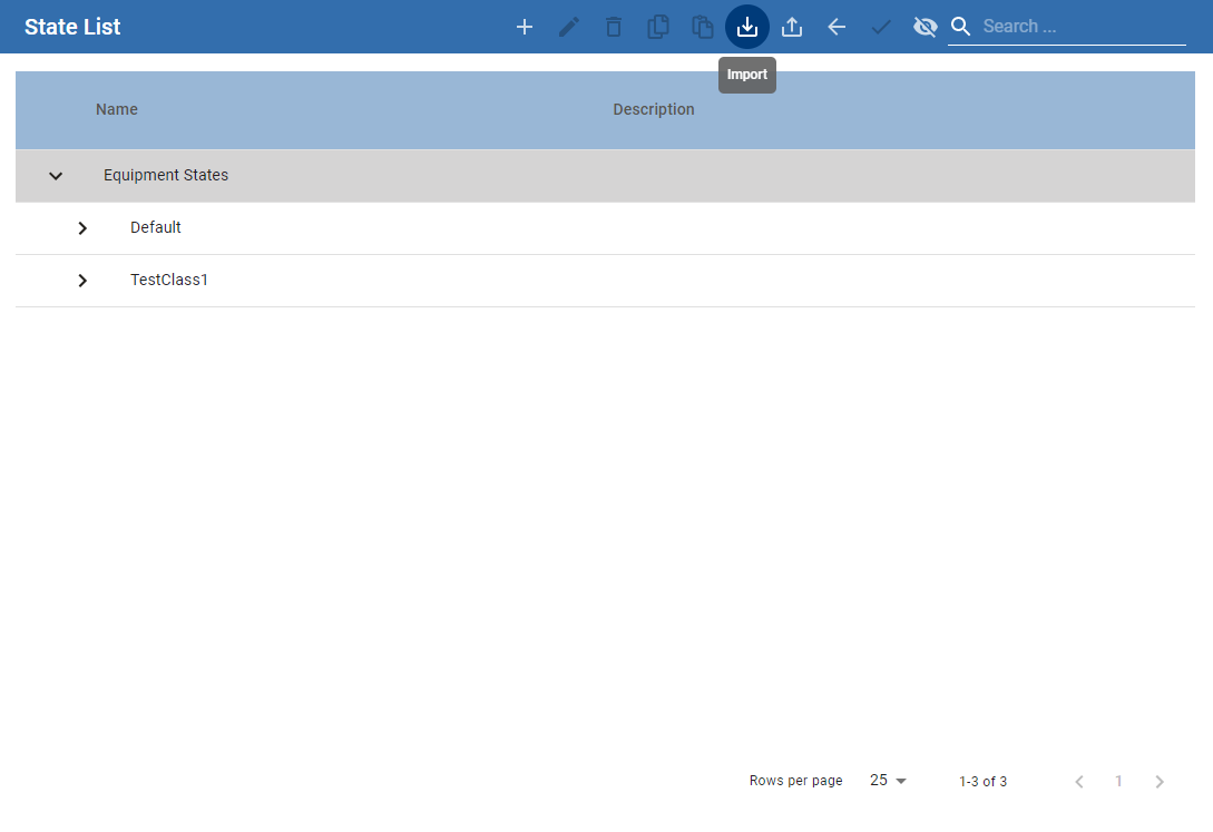
Import
- To import, select Equipment States and click Import.
- A file save dialog box will appear. Select the file to be imported and click Open.
Sepasoft MES Module Suite