Sepasoft MES Module Suite
Determining Downtime
Determining when a production line should be considered as running or in a down state is an important step in implementing OEE. For a simple process, determining the line state may be a trivial exercise, but for a complex multi-process work-center type of production, it may be not be so obvious. The OEE Downtime Module provides a flexible equipment hierarchy model (production model) and a number of downtime detection modes that can be used to automatically determine which cell downtime event caused a line to be down. These modes and the model accommodate a wide variety of manufacturing processes. A detailed description of each method along with the situations where it can be used is provided.

|
All of the downtime detection modes can be applied at any line level (main line or sub-line). Considerations: Cell Group cannot see downtime events outside of its immediate children.
Because the Group only sees downtime events in its children, it cannot see what is happening on the rest of the Line. |
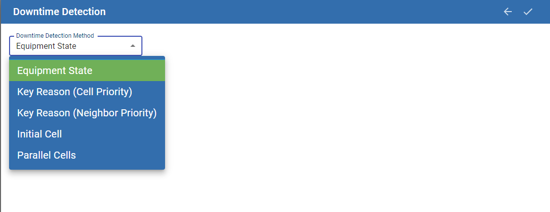
OEE Downtime Detection Method selections
in the MES Equipment Manager (Perspective)
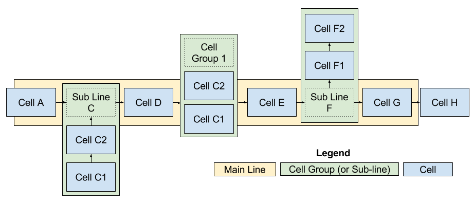
Sub-Lines and Cell Groups
In OEE Downtime, Cell Groups provide a mechanism for modeling complex process lines. A cell group can be used to model parallel cells where any one of a number of cells can perform the same process. Cell Groups can also be used to model sub-lines where sub-assemblies may be introduced into the line and added to the main assembly, or parts produced on the line go to different final sub-lines depending on work order requirements. All these scenarios can be modeled in the equipment hierarchy (production model) and all the downtime detection modes available for the main line are also available to cell groups.
From this point on in this section, 'Line' will be considered as representing either the Main line or a Sub-Line (Cell Group).
Equipment State Mode
This mode determines the line state (main or sub) from the provided state tag path. Use this method if the line state will be determined from a single state tag and not derived from the state of cells on the line.
|
|
It is still possible to bring in a state tag at the line level even if another downtime detection method is chosen. An active (Planned or Unplanned Downtime) type state on this tag will be used for the cause of line downtime in place of the derived reason. You might consider using this for downtime events that are general to the line and not specific to a cell such as 'Line E-Stop Pulled'. |
Parallel Cells Mode
This mode is available at the line level and also for Cell Groups, and allows you to model part of a production line where any of a number of cells can perform the same process as material proceeds down the line.
Parallel Cells in a Cell Group
When you have two or more cells that can do the same process and material can flow through any of these cells, configure the cells as part of a cell group. The Minimum Cells Running Threshold field allows you to define how many cells must be running in order for the Cell Group as a whole to be considered as Running.
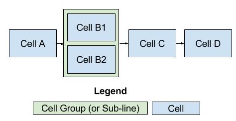
Parallel Cells in a Cell Group
Parallel Cells under a Line
When modeling a process, such as a cluster tool, where multiple cells may be running at any time, you can set the downtime detection mode to Parallel Cells at the line level. The cell that causes the number of running cells to drop below the Minimum Cells Running Threshold will be assigned as the cell causing the line downtime along with its reason.
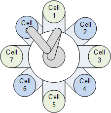
Cluster Tool
Initial Cell Mode
This mode picks the cell within the line (main or sub) that goes down first for an unplanned downtime event. When a cell first goes down, the date and time is recorded. If multiple cells are down, each will have its own date and the time it went down. The date and time for each down cell is looked at to determine the initial cell that went down and that cell will be assigned as the cell causing the line downtime along with its reason. If the initial cell restarts, then the other down cells are looked at in the chronological order that they went down. If there are two or more cells that went down at the same time, then the order that they appear in the designer will be used to determine the cell to blame.
If there are no cells down for an unplanned or planned reason, then the line will return to running state.
This method should be used if any cell is down, then all other cells have to stop. A continuous liquid mixing process where at each cell, new ingredients are added or mixed or some other action is being performed fits into this category. If one cell stops, then all other upstream cells have to stop because there is nowhere to put the liquid and all downstream cells have to stop because there is no liquid to process. In this case the first cell that stopped for an unplanned reason is the cause for all other cells to stop.
Key Reason Mode
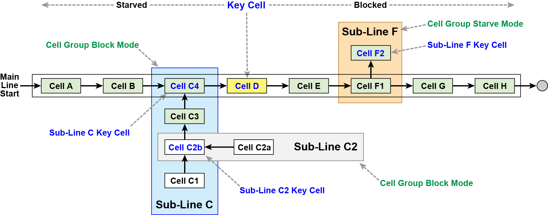
When there is a main process cell within a line or sub-line, such as a Filler, that you can say 'when the filler is running, the line is running, but when the filler is down, the line is down', then the Key Reason downtime detection methods (Cell Priority or Neighbor Priority) may be used. Both methods look at the flow of the line to determine the cause for the line or sub-line being down, the subtle differences between the modes are documented further below.
Creating the Key Cell
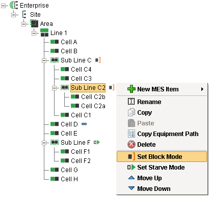
When using the Key Reason mode at the main line level, one cell must be defined as the Key Cell by right-clicking on the cell and selecting Set Key Cell. When the Key reason mode is used for a sub-line, the Key cell is automatically selected (see Key Reason on a Cell Group).
- When the key cell is running, then the line (main or sub) is considered to be running. When the key cell goes down, the line (main or sub) is considered to be down.
- If the key cell is down for an Unplanned Downtime type state, that state is considered to be the cause of line downtime.
- If the key cell is down for any other reason, the cells adjacent to it will be checked for an Unplanned Downtime type state. The direction in which the cells are checked is dependent upon whether the state type of the key cell state is set to BLOCKED or STARVED. In a STARVED state, the cells upstream from the key cell will be checked. In a BLOCKED state, the cells downstream of the key cell will be checked. If the key cell state is IDLE, the key cell state will be used for the line state.
- If the cell that caused the line downtime restarts but the key cell is still blocked or starved, the cause of line downtime will be re-evaluated based on the type of Key Reason selected (Cell Priority or Neighbor Priority)

|
If the key reason downtime detection mode is unable to determine the cause of downtime event, one of the following reasons will appear.
|
|
|
The mode of the line must have Include in OEE set to True (configured in Mode Class of the OEE section in the MES Equipment Manager component) for Key Reason detection method to work. See Equipment Modes and States page for various OEE settings. |
The Key Cell is identified in the production model by the![]() icon.
icon.
Key Reason on a Cell Group
When a key reason detection mode is used for a Cell Group, the key cell within the cell group is automatically selected based on the selected Block or Starve mode and cannot be changed. To have the first cell in the cell group be the key cell, right click on the cell group and select Set Block Mode. To have the last cell in a cell group be the key cell, select Set Starve Mode.
Cell Priority
- When the key cell is BLOCKED, the downstream cell closest to the key cell that is down for a recordable downtime reason is considered to be the cause of line downtime.
- When the key cell is STARVED, the upstream cell closest to the key cell that is down for a recordable downtime reason is considered to be the cause of line downtime.

|
In the event an unexpected blocked or unexpected starved is encountered on a cell group, and that cell group has a previous down state recorded, the system uses the last known down state over unexpected blocked/starved. |
Neighbor Priority
- When the key cell is BLOCKED, the downstream cells are checked starting with the cell furthest away from the key cell. The first cell found to have an unplanned downtime event is considered as the cause of line downtime.
- When the key cell is STARVED, the upstream cells are checked starting with the cell furthest away from the key cell. The first cell found to have an unplanned downtime reason is considered as the cause of line downtime.
- Whenever the state of the cells changes even after line downtime has been logged, the cells will be re-evaluated and the cause of line downtime updated.
- This mode requires that the state of contiguous cells between the key cell and the down cell are also set to the Starved or Blocked state.
|
|
When using the Key Reason method, it is expected that state changes from the cells will ripple along the line. If the Key Cell is blocked, but the adjacent cell is still running, Key Reason will not pick up any faulted cells beyond the running adjacent cell as the cause of line downtime. If the Key Cell is blocked, but the adjacent cell is still running, Key Reason will use the last fault of the running adjacent cell as the cause of line downtime. This handles the case when a event occurs and clears at a cell that results in a delayed block condition at the key cell. The same is true for starved conditions. It is important that state tags for any contiguous cells between the key cell and the cell causing downtime show a Blocked or Starved state for Key Reason detection to work (unless they are disabled). |
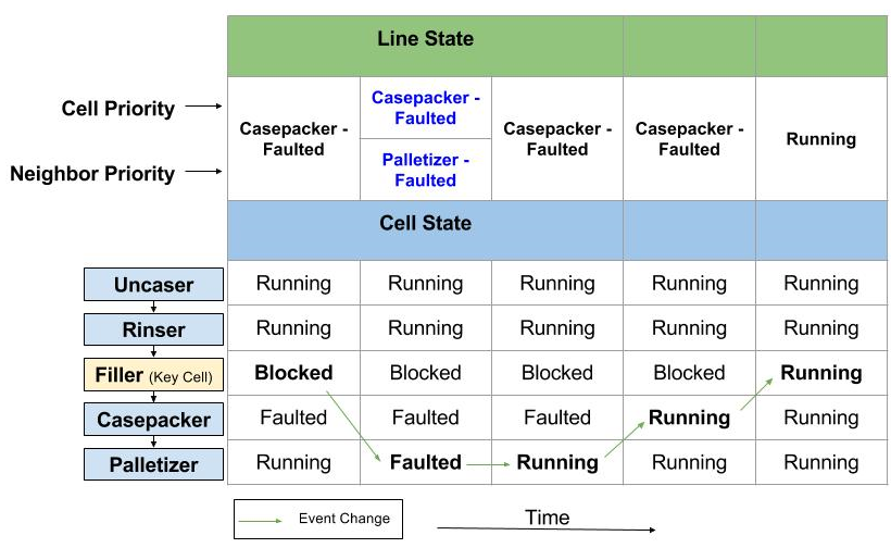
Scenario 1 - Casepacker Fault Followed By Palletizer Fault
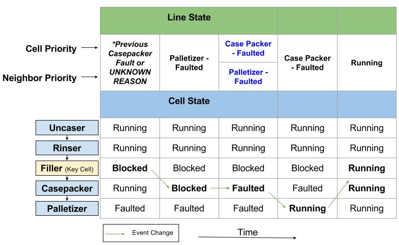
Scenario 2 - Palletizer Fault Followed By Casepacker Fault
*Line State depends on if the Casepacker was previously down. If it was then, that downtime reason will be used instead of Filler - BLOCKED FOR UNKNOWN REASON.
Sepasoft MES Module Suite