Sepasoft MES Module Suite
Basic Control Chart
Build a simple control chart from scratch. You may want to put a control chart on an HMI window and you don't want all of the settings that come along with the built-in control charts window.
The major steps to do this are outlined below:
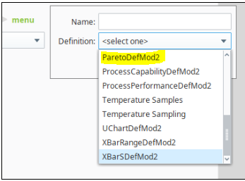
- Create a Sample Definition for the Pareto chart. Name the Sample Definition something to indicate 'pareto': ParetoDefMod2.
Learn about creating Sample Definitions in Sample Definition Manager
- Create a Stored Setting based on that Sample Definition. Add the Stored SPC Selector to a window (Currently Vision only). Create a new stored settings. Name it. You'll enter this name in the props for the SPC Controller. This is what creates the association between the Sample Definition and the SPC Controller. Sample Definitions have a one-to-many relationship to Stored Settings and SPC Controllers.
- Open Ignition Designer and create a View. Add the SPC Controller to the View.

The SPC Controller component is invisible at run-time and at design time displays as an SPC Controller icon in Ignition Designer.
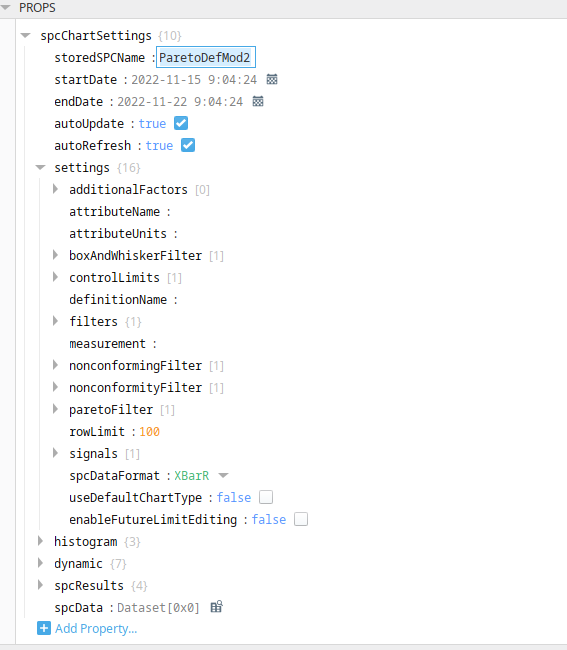
- In the SPC Controller property palette, under spcChartSettings, enter the name in storedSPCName. Then, the property values under Settings auto-populate.
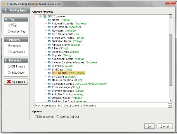
Make sure you have samples entered in and approved. Otherwise, you won't see any data in the control chart. Now that we have the data, let's add the control chart to the window. Drag on the Pareto Chart from the SPC tab of the Component Palette on the window. Bind the SPC Results property of the control chart to the SPC Results from the SPC Controller.
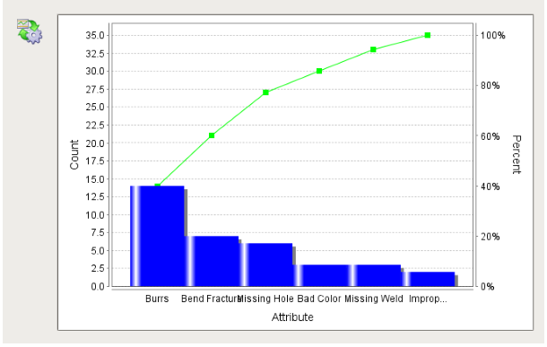
Press OK. You should see some data in the pareto.
There are other settings you can configure on the control chart. With the auto refresh property set to true on the SPC controller, the pareto will continue to update as new data is added. You can perform the same process for any other sample definition and any control chart.
Sepasoft MES Module Suite