Sepasoft MES Module Suite
Production Counters for OEE Metrics
OEE metrics use production counters. OEE calculations are done at the Line and Cell levels.
There are 4 types of counters:
- Infeed
- Outfeed
- Reject
- General
To get the best results for OEE calculation behavior:
- When there is only one type of MES Counter for the Line (either just an Infeed counter or just one or more Outfeed counters), it/they must be created on the Line in the Production Model.
Note that having only one counter, created on a Cell in the Production Model, does not allow the Line OEE calculations to be calculated correctly.
- When there are both an Infeed counter and an Outfeed counter (both on the Line, both on Cells, or a mix), make sure that the Infeed Count Equipment and Outfeed Count Equipment in the Material Definition both point to the locations where the MES Counters were created in the Production Model.
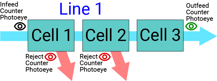
Serial Cells
In these scenarios, each cell in the production line flows into the next cell, in series (there are no branches to the production line).
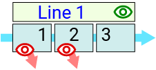
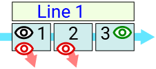
The diagram to the right shows all of the possible physical placements for photoeye detectors used to count the infeed, outfeed and reject parts in the examples below. The diagrams in the table below show where the MES Counters were created (which equipment).
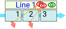
The table below has some examples of various production line configurations, along with the OEE behavior that results based on how MES Counters are created in the Production Model and how the Material Definition counter selections are made.
| # | Scenario |
Production
Model |
Material
Definition |
OEE Behavior OEE Quality = (OEE Infeed - OEE Reject) / OEE Infeed |
|||||
| MES Counter Location | Infeed Count Equip. | Outfeed Count Equip. | |||||||
|---|---|---|---|---|---|---|---|---|---|
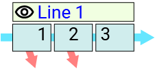
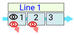
| 1 |
|
Infeed Line 1 |
Outfeed n/a |
Reject n/a |
Line 1 |
Line 1 |
[VALID]
|
||
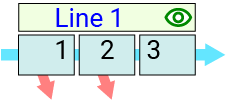
| 2 |
|
Infeed n/a |
Outfeed Line 1 |
Reject n/a |
Line 1 |
Line 1 |
[VALID]
|
||
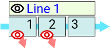
| 3 |
|
Infeed Line 1 |
Outfeed n/a |
Reject
Cell 1
|
Line 1 |
Line 1 |
[VALID]
|
||
| 4 |
|
Infeed n/a |
Outfeed Line 1 |
Reject
Cell 1
|
Line 1 |
Line 1 |
[VALID]
|
||
| 5 |
|
Infeed Cell 1 |
Outfeed n/a |
Reject Cell 1 and Cell 2 |
Cell 1 |
Line 1 |
[VALID]
Included in Sepasoft Versions:
|
||
| 6 |
|
Infeed n/a |
Outfeed Cell 3 |
Reject Cell 1 and Cell 2 |
Line 1 |
Cell 3 |
[VALID]
Included in Sepasoft Versions:
|
||
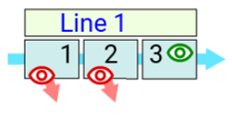
| 7 |
|
Infeed Cell 1 |
Outfeed Cell 3 |
Reject n/a |
Cell 1 |
Cell 3 |
[VALID]
|
||
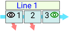
| 8 |
|
Infeed Cell 1 |
Outfeed Cell 3 |
Reject
Cell 1
|
Cell 1 |
Cell 3 |
[VALID] Ideal configuration:
|
||
| 9 |
|
Infeed n/a |
Outfeed Line 1 |
Reject Line 1 |
Line 1 |
Line 1 |
[VALID]
|
||

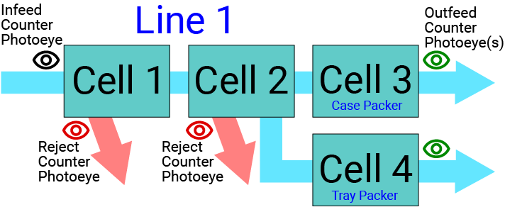
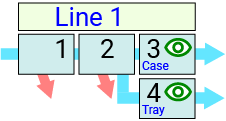
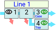
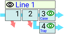
Parallel Cells
In the scenarios below, the production line utilizes divergent (parallel) packaging cell options.
In this example, items manufactured in previous cells can be diverted into one of two packaging cells, Case or Tray, for shipping products either by the case or by the tray, based on the demand for each in the market.
The diagram to the right shows all of the possible physical placements for photoeye detectors used to count the infeed, outfeed and reject parts in the examples below. The diagrams in the table below show where the MES Counters were created (which equipment).
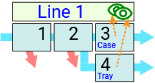
The table below has some examples of various production line configurations, along with the OEE behavior that will result based on how MES Counters are created in the Production Model and how the Material Definition counter selections are made.
| # | Scenario |
Production
Model |
Material
|
OEE Behavior | |||
| MES Counter Location | Infeed Count Equip. | Outfeed Count Equip. | |||||
|---|---|---|---|---|---|---|---|
| 10 |
|
Infeed n/a |
Outfeed
Line 1
|
Reject n/a |
Line 1 |
Line 1 |
[VALID]
Note: Runs using the Case Packer will drive Case Packer Outfeed counter up. Runs using Tray Packer will push Tray Packer Outfeed counter up.
|
| 11 |
|
Infeed n/a |
Outfeed
Cell 3
|
Reject n/a |
Line 1 |
Cell 3*
|
[NOT VALID]
Note: Place both of the Outfeed counters on Line 1 instead.
|
| 12 |
|
Infeed Cell 1 |
Outfeed
Cell 3
|
Reject n/a |
Cell 1 |
Cell 3*
|
[VALID]
|
| 13 |
|
Infeed Line 1 |
Outfeed
Cell 3
|
Reject n/a |
Line 1 |
Cell 3*
|
[VALID]
|
Sepasoft MES Module Suite