Sepasoft MES Module Suite
What is a Sample Definition?
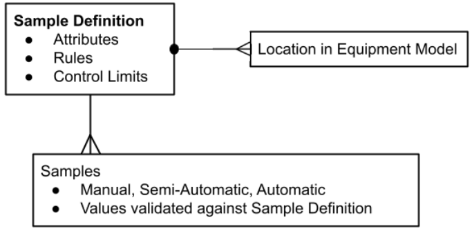
A Sample Definition object holds all of the information defining a type of sample. This information includes: attributes that define the sample, locations that specify where the samples are taken including Control Limits and Rules that can detect common and special cause variation.
A Sample Definition has a one-to-many relationship to samples taken and locations.
You create Sample Definitions in the Sample Definition Manager, see below.
A Sample Definition includes:
| Attribute List: | Can include: name, description, isRequired, datatype, chart type, order, measurement count, format, units, weight, default value, minimum value and maximum. |
| Locations: | Select locations set up via Equipment Manager. For each location, you can set interval type, coming due and over due thresholds, interval, duration, enable and auto approve. |
| Rules: | Rules define the signal notifications that can indicate abnormal changes in the process. |
| Control Limits: | Sets what a process is capable of producing as well as tolerances and specifications to specify how the product should perform. |
 |
The system verifies each value during sample collection against the Attribute settings such as, datatype, format, minimum and maximum values. |
Capturing Sample Data
Sample data can be captured in a number of different ways:
- Tags can be configured to automatically capture sample data by using the Automatic Tag Sample Collector.
- Sample definitions can be configured to take samples manually in several ways, shown below.
- Scripting can be employed to create samples.
|
|
The SPC engine performs the necessary calculations based on the Control Limits, Out of Control Signals and Misc. Calculations that have been defined and enabled for that sample no matter how the sample is taken. |
| Manual: | The Sample Definition defines the interval at which the samples should be taken. When set to Manual, you need to create a mechanism to take samples using scripting. See the Statistical Process Control (SPC) Tutorial. |
Automatic: | This is not an actual setting but more of a concept used when talking about an SPC setup. Automatic Interval Types include Once at Production End, Once at Production Start, Shift Change, Time Interval for days, hours, minutes and seconds. |
Semi-Automatic: | This is not an actual setting but more of a concept used when talking about an SPC setup. Using an automatic interval without Auto Approve = True and/or Manual set for Interval Type using collection by scripting sets up semi-automatic sample collection. |
Sample Definition Scripting Functions
Creating Sample Definitions
Requirements to complete these steps:
- MES Modules installed in the Ignition Gateway: SPC Module and Production Module.
- Add the SPC Sample Definition Manager to a window (currently Vision only components available) in the Ignition Project file.
Use the SPC > Sample Definition Manager to complete these steps:
For component reference doc, see SPC Sample Definition Manager.
Check out some examples of Sample Definitions settings based on the chart to use:
- Sample Definition Settings for Box and Whisker Chart Type
- Sample Definition Settings for Histogram Chart Type
- Sample Definition Settings for Individual Chart Type
- Sample Definition Settings for Pareto Chart Type
- Sample Definition Settings for Process Capability Chart
- Sample Definition Settings for Process Performance Chart
- Sample Definition Settings for XBar Chart Type
In Sample Definition Manager:
- Under General, click New Sample Definition Class. To add to the root level, right click in a blank area of the hierarchy tree window.
- Select the class and then click under General, click New Sample Definition.
- Enter the General settings:
Sample Definitions include a section for general settings:
| General Settings | Description | ||
|---|---|---|---|
| Name | Enter a name for the sample definition. You can change this name after saving. | ||
| Description | Sample definition description | ||
| Measurement Count | This number becomes the upper limit for the measurement count for each Sample Definition Attribute. Example: If Measurement Count is set to 5 here and you set an attribute within this definition to 10, then, only 5 samples is allowed to be collected.
| ||
| Interval Type | Defines how the samples are scheduled. If set to an automatic interval, such as time-based or schedules, and Auto Approve = True, then system automatically takes the sample. Interval Type is set in two places: Sample Definition and Location. The top-level Sample Definition settings is used as the default setting and when the definition is associated with testing location(s) in the Location settings, the default is overwritten at the Location level if needed. This is useful when the Sample Definition is used for multiple locations and the interval is different at each location. | ||
| Coming Due | In minutes by default | ||
| Over Due | In minutes by default | ||
| Interval | The unit based on the Interval Type. The interval for automatically scheduling samples. | ||
| Duration | The number of minutes needed to take a sample. This sets the ScheduledFinish field for the Sample. | ||
| AutoApprove | Sets the sample values to be approved automatically. |

Next, see below on how to add attributes, select locations, selecting rules, and select control limits.
Attributes in a Sample Definition
Some examples of attributes include pH, temperature, viscosity, weight, non-conformities, and nonconforming items. From here, the name, description, datatype, format, default value, minimum value, and maximum value can be defined.
To add attributes to a Sample Definition:
- Select a definition in the Definition List tree.
- Under Sample Definition Settings, click Attribute List.
- Click New.
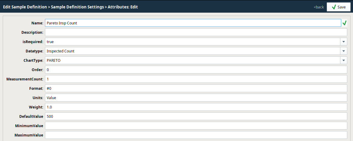
| Attribute Settings | Description | ||
|---|---|---|---|
| Name | Names can have spaces and special characters. | ||
| Description | Attribute summary description | ||
| isRequired | Use isRequired set to True, to ensure values are entered before saving. Version Dependent
| ||
| Datatype |
| ||
| ChartType |
| ||
| Order | Used is in the Sample Entry component, where it determines the order in which the attributes display. | ||
| Measurement Count | Sets the number of samples to take for the system to consider the counts as a full sample. | ||
| Default Value | Sets the default value for a measurement. | ||
| Minimum Value | Optional - Sets the minimum value of measurement data. | ||
| Maximum Value | Optional - Sets the maximum value of measurement data. | ||
| Format | Optional - The format string for this attribute's display. Used to verify formatting values on the control charts and that entered data is correctly formatted. | ||
| Units | Optional - Sets the measurement to a standard quantity. | ||
| Weight | Optional - Used for the Pareto chart to determine importance. For example, you have Scratched and Cracked. Cracked is a bigger deal so you would give it a higher weight here. |
Locations
Locations are where the samples are taken. Locations can be created under Areas and Lines in the Equipment Model in Equipment Manager.
| Location Settings for Sample Definitions | |||
|---|---|---|---|
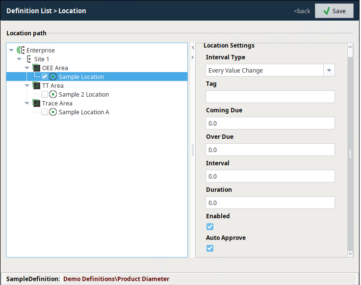
Location Path: Equipment-model browser provides a visual representation of the equipment path(s) to Location(s). Locations are configured in Equipment Manager. | |||
Interval Type Interval Type is set in two places: Sample Definition and Location. The top-level Sample Definition settings is used as the default setting and when the definition is associated with testing location(s) in the Location settings, the default is overwritten at the Location level if needed. This is useful when the Sample Definition is used for multiple locations and the interval is different at each location. 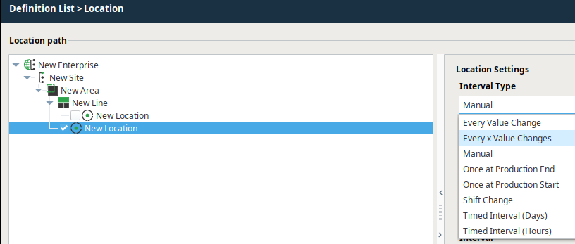 | For more information
| ||
Tag: Meta data type of tag. This is not a reference to a tag in the Tag Browser. | 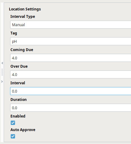 | ||
Coming Due: The amount of time before the sample is taken the system sets the sample as Coming Due. | |||
Over Due: The amount of time after the sample is taken the system sets the sample as Over Due. | |||
Interval: Interval unit based on the Interval Type | |||
Duration: The amount of time from beginning to end of the process that takes the sample. | |||
Enabled: Makes the sample definition active. | |||
Auto Approve: When set to True, the system automatically takes the sample for time- and schedule-based Interval Types. | |||
For more information
|
|
Selecting Rules (to generate Signals)
Under Sample Definition Settings, click to select one or more Rules from the list. Any selected Rules will be available to include on the control charts and will also be included in the automatic evaluation of out of control conditions of the sample data, to generate Signals that can notify factory personnel or other system components of out-of-spec production line behavior.
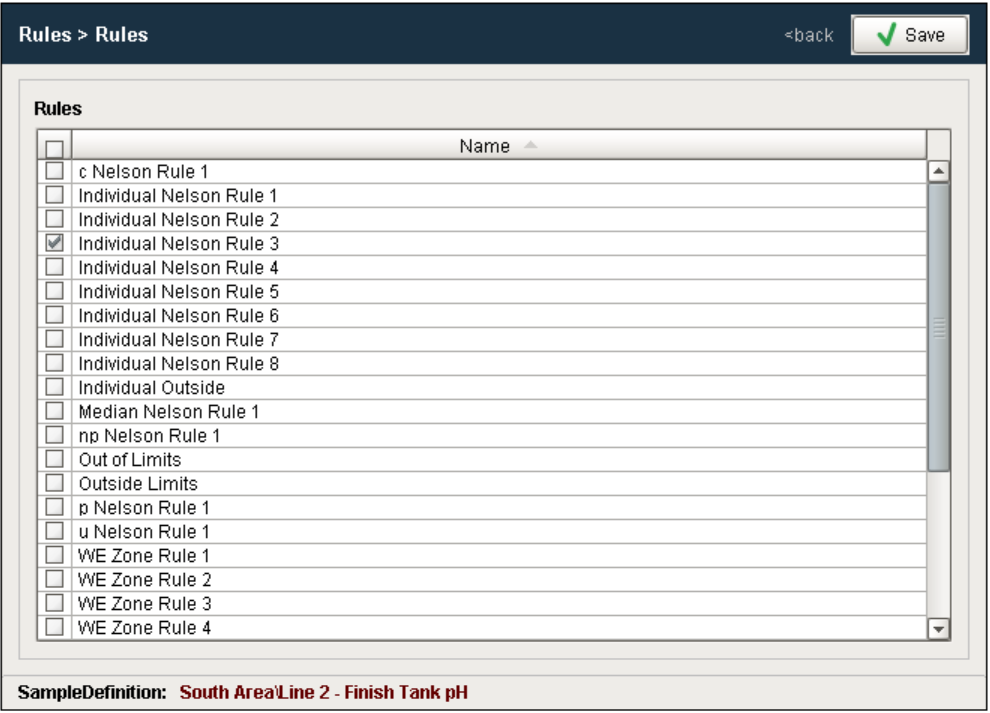
When a new project is created, the default Rules options are also created but they can be modified, added to or even removed.
Keep in mind that each Rule is associated with a particular control chart. For example, Individual Outside is associated with, and can only be used with, the Individual chart. This is because the calculation and control limits used to determine if a sequence of individual values are out of control is specific to the Individual chart.
For more information
|
|
Selecting Control Limits
Under Sample Definition Settings, click to select one or more Control Limits from the list (these are often selected in pairs – one for an upper limit and one for a lower limit). Any selected Control Limits will be available to include on the control charts and will also be included in the automatic evaluation of out of control conditions of the sample data.
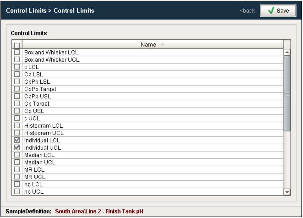
When a new project is created, the default Control Limit options are created, but they can be modified, added to or removed. Keep in mind that each Control Limit is associated with a particular control chart. For example, XBar UCL is associated and can only be used with the XBar Chart. This is because the calculation used to determine the XBar UCL value is specific to only the XBar Chart.
After all the desired settings have been defined, select Save to commit all the changes or Cancel to undo any changes that have been made. After a Sample Definition has been created, samples based on them may begin to appear or can be manually added depending on the Interval setting.
For more information
|
|
Sepasoft MES Module Suite